
coal processing flow disgram manufacturer Grasping strong production capability, advanced research strength and excellent service, Shanghai coal processing flow disgram supplier create the value and bring values to all of customers.
 WhatsApp)
Flow diagram of a typical petroleum refinery. The image below is a schematic flow diagram of a typical petroleum refinery that depicts the various refining processes and the flow of intermediate product streams that occurs between the inlet crude oil feedstock and the final endproducts.
How a Coal Plant Works. ... condensed back into water and returned to the boiler to start the process over. Here''s a reallife example: The Kingston Fossil Plant near Knoxville, Tenn., burns coal to heat its boilers to about 1,000 degrees Fahrenheit to create highpressure steam. The steam is piped to the turbines at pressures of more than ...
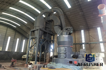
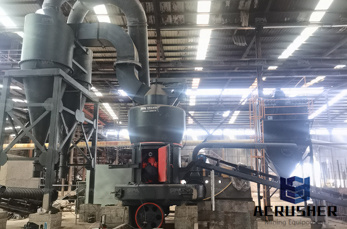
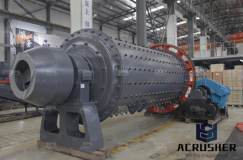
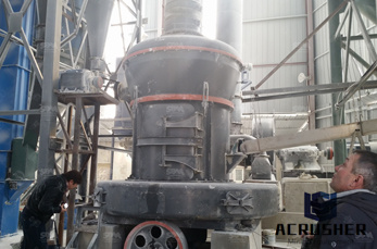
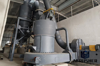
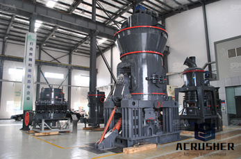
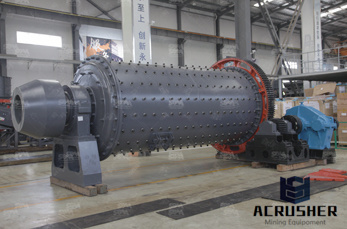
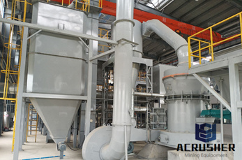
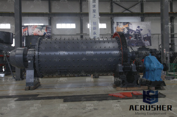
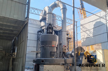
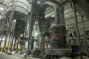
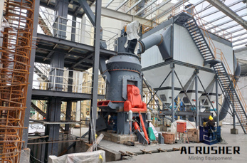
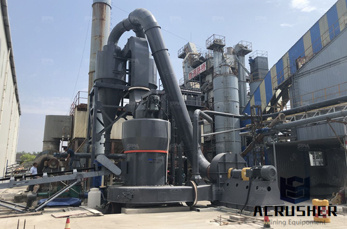
Home > Products > coal processing flow chart . Mobile Crushing Plant. Stationary Crushing Plant. Grinding Mill. Washing Screening. Three in One Mobile Crusher. Mobile VSI Crusher. Mobile VSI Crusher Washer. Mobile Crusher Screen. Mobile Impact Crusher. Four in .
Oxyfuel Coal Combustion Power Plant System Optimization. This airfired power plant releases 350 tCO2/hr. Figure 1 shows the process flow diagram for both the airfired...Current conventional coalfired boiler plants burn coal...
Jun 16, 2014· Steam Flow DiagramSteam Flow Diagram 9. Coal to ElectricityCoal to Electricity 10. • A coal handling plant is the area of the thermal power plant where the raw coal is brought from the coal mines and is processed into a form that can fed into the boiler. 1. Transportation System 2. Coal Crusher 3. Coal Storage Area 4. Pulverizer 5.
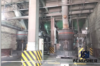
Figure 1: A Simplified CoaltoSNG Block Flow Diagram. The economic viability of producing synthetic natural gas (SNG) through coal gasification is heavily dependent on the market prices of natural gas and the coal feedstock to be used, in addition to the capital cost of the gasification plant. ... SNG from Coal: Process Commercialization.
Coal Beneficiation Process Diagram # – Coal Processing Flow Chart, with 38 Similar files. Free Flowchart Templates Home › Coal Processing Flow Chart › Gallery. Coal Beneficiation Process Diagram. File#: Coal Beneficiation Process Diagram.
coal mining process flow chart diagram , The process flow diagram Image Mining Technology Burton Burton is located in Queensland''s Bowen Basin, 150km southwest of, .
coalfired power plant. This process flow diagram illustrates the three turbine groups (high, intermediate and low pressure turbine), the condenser, the feed water tank, the four low pressure and two high pressure preheaters and the subcomponents of the steam generator. The steam generator, as exemplarily shown
A process flow diagram for a typical coal cleaning plant is. Chat Now. Hydrogen Production from Fossil Fuels eolss. are detailed including process flow diagrams. A brief review of the efficiency ... Following natural gas and oil is the process of steam gasification of coal. In these.
Coal Mining Process Flow Chart Diagram Coal Processing Diagram # – Coal Mining Flow Chart, with 37 More files. Coal Mining Process Flow Chart Diagram Coal Processing Diagram # – Coal Mining Flow Chart, with 37 More files. Free Flowchart Templates
Coal Preparation PlantsCOAL PREPERATION(PREP) PAGE Contains CoalPrep InformationA Coal preperation plant, nestled amongthe mountains. Coal Preperation plants generally use gravityprocess equipment to separate the refuse from the product (coal). Coal has a specific gravity between 1. 35 and 1. 5, while therefuse rock has a Specific Gravity of 2. 1 to 2. 3. Heavy Media isthe most popular .
Coal processing has two forms, here descripe flow chart of coal processing plant: Industrial process is the coal after the coal crusher, with the belt conveyor to quantitative feeder, to pressure the ball machine feeding by quantitative feeder uniform, sometimes need to improve the coal briquette strength, therefore, quantitative feeder and intermediate pressure ball machine can also add ...
generally be divided into four basic phases: initial preparation, fine coal processing, coarse coal processing, and final preparation. A process flow diagram for a typical coal cleaning plant is presented in Figure In the initial preparation phase of coal cleaning, the raw coal is .
The hydrocarbons produced by FT process can be refined and used in place of more conventional liquid fuels derived from crude oil. Synthetic fuel can be produced by a variety of gasification methods, with gastoliquid (GTL), coaltoliquid (CTL) and biomasstoliquid (BTL) being the most widespread. Process Flow Diagram
Coal gasification Diagram is intended to be representation and not to be viewed as actual process flow diagram. Lock hopper Gasifier Oxygen Nitrogen Electricity Steam Syngas Turbine Syngas for: Grey water H2S Syngas Grey water tank Sulphur removal Feed types: Petroleum coke Coal Heavy oil Residue Refinery sludges Chemicals Hydrogen Ammonia ...
Multotec''s Coal Industry Flow Sheet. We use cookies to improve your experience on our website. By using our site you agree to Cookies Policy
Figure 1 shows a simplified block flow diagram (BFD) of a methanol (MeOH) plant based on coal feedstock. Syngas from the gasifier is cooled by generating high pressure (HP) steam in the high temperature (HT) gas cooling system before being water quenched and scrubbed to remove fine particulates. The scrubbed syngas then goes through a sour water gas shift (WGS) to adjust the H2to .
Nov 06, 2013· Coal Washing Plant Flow Diagram Uk XSM has been serving the aggregate crushing grinding industry for over 12 years, it is one ...
2. Basic Schema of the Rectisol® Process ¾Block Flow Diagram and Simplified Process Flow Diagram ¾Achievable Product Quality of the Rectisol® Process 3. Polygeneration Concepts with the Rectisol® Process ¾Multi Products with one Acid Gas Removal System 4. CO2 Emissions Clean Energy ¾CO2 Capture with the Rectisol® Process 5.
Coal based power plant SlideShare. Jun 16, 2014 Steam Flow DiagramSteam Flow Diagram 9. Coal to ElectricityCoal to Electricity 10. • A coal handling plant is the area of the thermal power plant where the raw coal is brought from the coal mines and is processed into a form that can fed into the boiler.
As shown in the process flow diagram, the coal is first slurried with water and fed to the first stage of the gasifier. Oxygen with a purity of 95% is provided from the Air Separation Unit (ASU) and the coal is partially combusted to maintain a temperature of 1370 °C.
The more details you give on your situation, the better we can help you. Leave your phone number if you would like us to call you.
Sep 03, 2013· The purposed operation of this plant is to improve the mine product recovery by collecting roof floor materials as wash feed, which usually dump as waste. This is a part of coal beneficiation to ...
WhatsApp)